
Battery Safety Knowledge Hub
Technical Risk
Thermal Propagation
A cell in thermal runaway is the source. Thermal propagation is the system problem.
The design objective is not simply to add more safety components. It is to understand how the initiating cell transfers energy or creates secondary faults, then interrupt the actual escalation pathway.
MAIN PROPAGATION PATHWAYS
Thermal propagation does not happen through one mechanism. A failing cell can expose the surrounding system through several thermal, mechanical and electrical pathways at the same time.
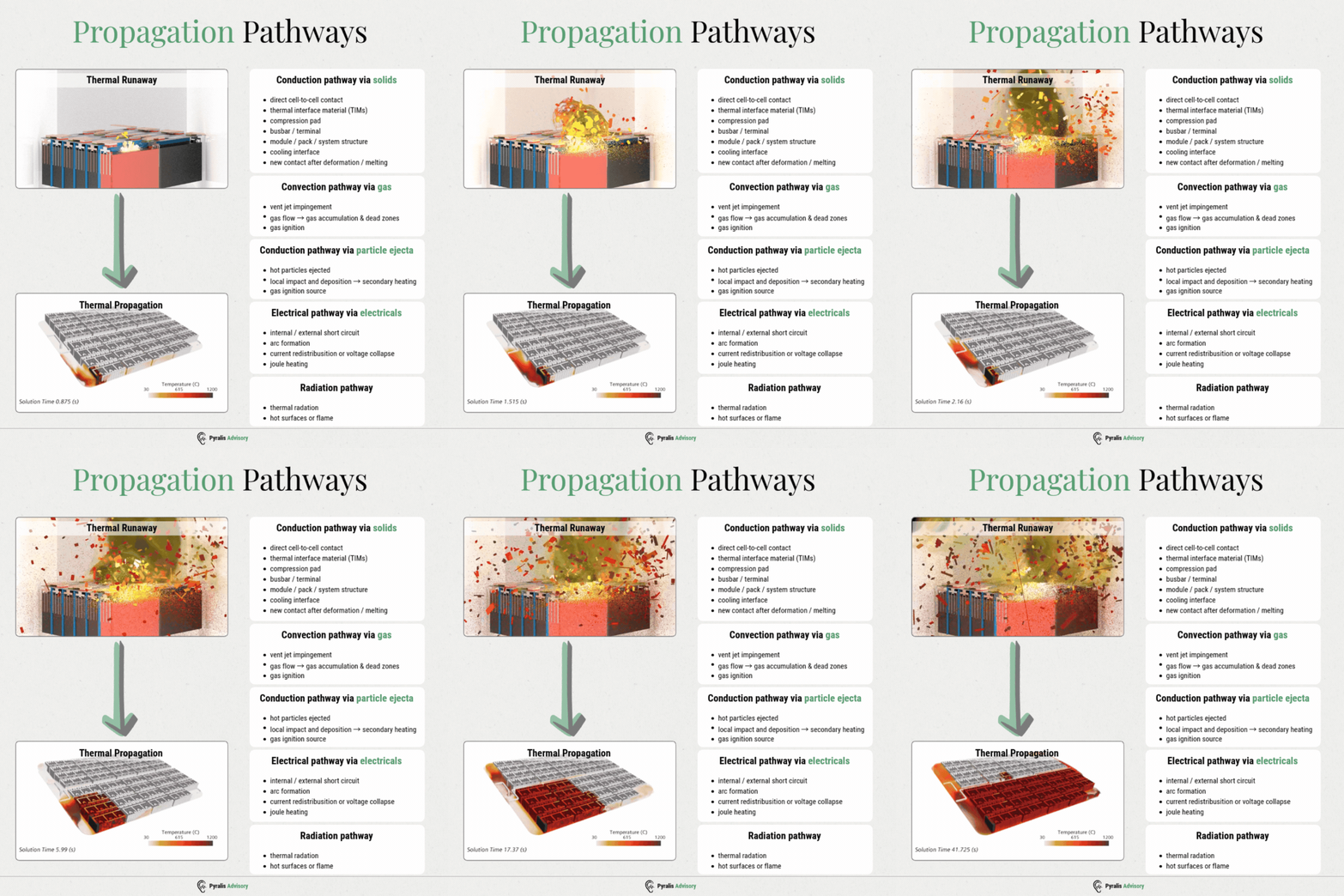
Conduction via Shared Interfaces
Heat transfers directly through cell-to-cell contact, compression structures, busbars, cooling plates, and other shared hardware. In tightly integrated systems, these interfaces often serve as efficient thermal bridges to adjacent cells.
Convection and Direct Hot-Gas Impingement
Hot vent gases and electrolyte vapours may flow directly onto adjacent cells or components. The combination of elevated temperature, high velocity, and localized exposure imposes significant thermal loads and accelerates propagation.
When ignition or sustained flame is present, neighbouring cells and system components are exposed to thermal radiation and direct flame. This pathway becomes increasingly significant as the event extends beyond the initial cell.
Thermal runaway may eject hot particles, molten material, cell fragments, or components of the electrode assembly. These materials can cause highly localized heating, damage protective barriers, and initiate further failure mechanisms.
Heat, ejected particles, and mechanical damage can compromise insulation and electrical connections. These failures may result in secondary short circuits, arcing, and additional sources of heat or ignition beyond the initial cell failure.
Released flammable gases may migrate and accumulate within modules, packs, racks, or enclosures. If both a flammable concentration and an ignition source are present, a cell-level event can escalate into a broader fire, deflagration, or explosion hazard.
DESIGN LEVELS
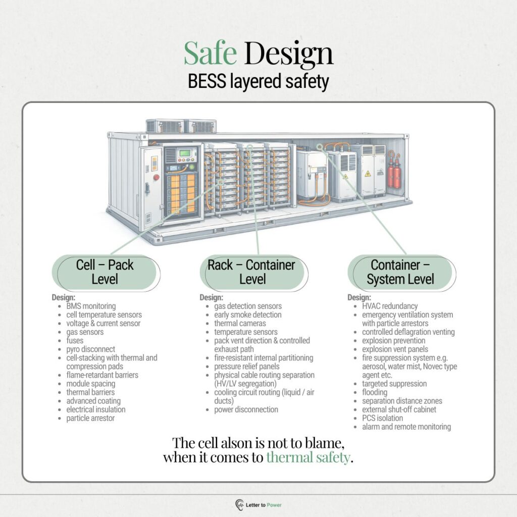
The first protective layer is the cell itself. Chemistry, cell design, usable state-of-charge (SOC) window, and venting behaviour determine the quantity of heat, gas, and material released during an initiating failure.
At this level, the objective is to prevent or delay failure propagation to adjacent cells. Cell spacing, barriers, compression design, cooling interfaces, and controlled vent paths are employed to interrupt primary propagation pathways.
The pack is responsible for managing emissions from the initiating module. Vent routing, electrical separation, internal partitioning, pressure management, and thermal design are implemented to prevent a localized failure from escalating to a pack-wide event.
At the highest level, the primary objective is containment. Separation distances, ventilation, pressure relief, suppression systems, monitoring, and emergency response protocols are utilized to prevent the event from spreading to adjacent racks, containers, equipment, or occupied areas.
MITIGATION QUESTIONS
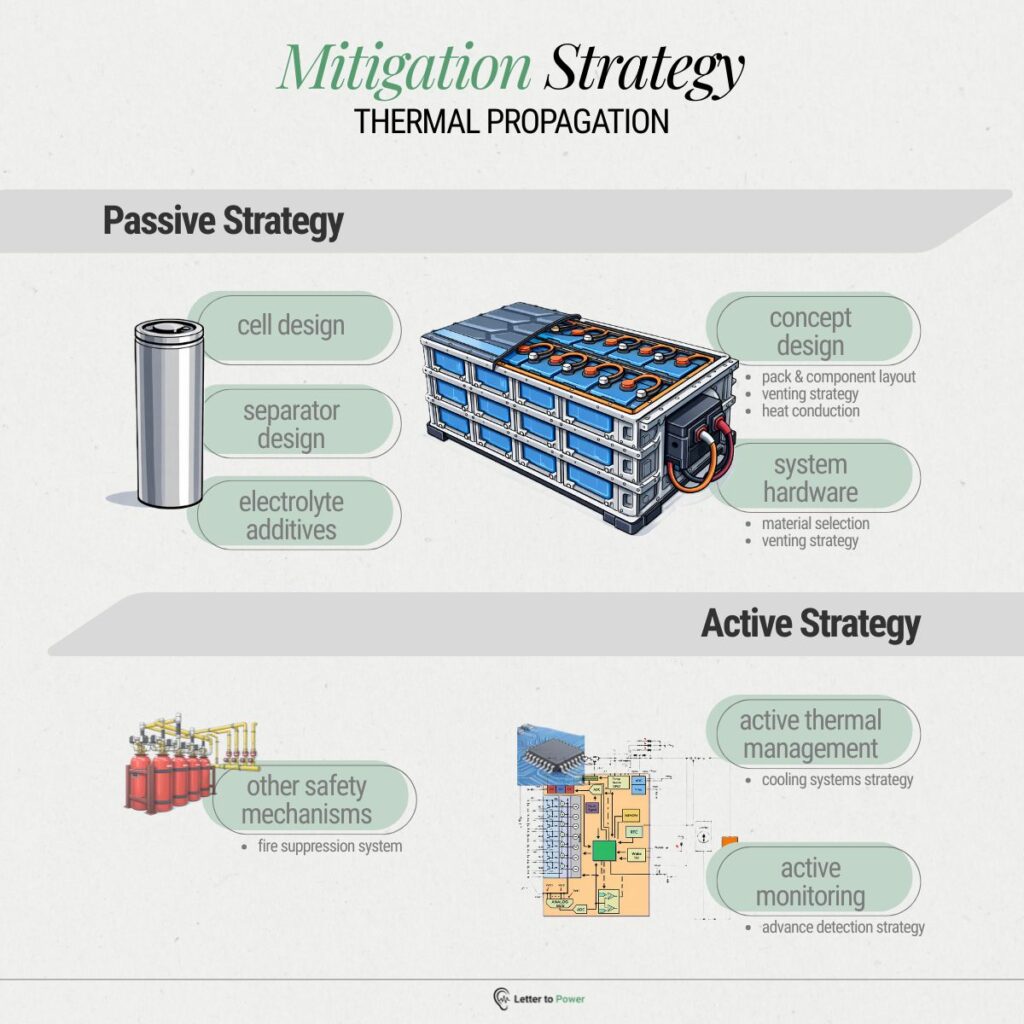
Prior to selecting a mitigation measure, it is essential to identify the mechanisms responsible for propagating the failure, such as conduction, hot gas, particles, radiation, electrical faults, or combinations thereof.
The propagation delay determines the intervention window and should be compared with detection, decision, and response times to assess whether active mitigation can be implemented rapidly enough.
A barrier is effective only if it blocks the relevant heat-transfer or failure propagation mechanism. Even a highly rated material may fail to protect the system if hot gas, particles, or conductive hardware bypass the barrier.
Gas and ejecta should be directed along a predetermined path away from vulnerable cells, electrical components, and confined volumes. If the system does not control this trajectory, the failure may exploit an unintended pathway.
Cooling can delay failure propagation by removing heat from adjacent cells, but only if it remains operational during the event. Therefore, fault logic, power supply, and coolant integrity are critical considerations.
Hot gas and conductive particles must not be permitted to contact busbars, connectors, or other high-voltage components, as this can result in insulation failure, short-circuiting, or arcing.
The thermal load persists after the main venting ceases. Residual heat, ongoing combustion, hot surfaces, and continued heat transfer to adjacent cells can still cause delayed propagation.
KEY PYRALIS PRINCIPLE
The best design is not necessarily the one with the most safety features. It is the one where the escalation pathway has been understood and deliberately designed against.
Sectors we support
Supporting organisations that design, test, evaluate, insure and shape battery and energy systems.
From battery developers and test facilities to insurers, system integrators and industry bodies.
BESS, Passenger & Commercial EV
Test Facilities, Standards & Industry Bodies
Battery Materials and Components
Fire protection & safety providers
Investors, Insurers & Due-diligence Teams
System integrators & OEMs

Let's start with focus session
Discuss a Battery Safety Problem
Battery safety problem, technical decision, commercial growth challenge or something in-between the two.